
Figure 4-4. Maximum Month Flows 0 2 4 6 8 10 12 14 16 02 46 8 10 12 14 16 Rainfall, in/mo Monthly Average Plant Flow, mgd . MMWWF = 12 mgd MMDWF = 6.2 mgd 1-in-10 year May Rainfall = 3.93 inches 1-in-5 year January Rainfall = 9.79 inches
 WhatsAppGet PriceGet A Quote
designing plant layout, which we will discuss later in the unit. But as we are discussing about the advantages of a good plant layout, we wee that a proper plant layout helps us in reducing cost of operation, which is very important for survival of any industry. A good plant layout, in general, has the following advantages. R O A D 3 5 4 1 2 6
WhatsAppGet PriceGet A Quote
Flow sheet print The flow sheet is printed showing the currently active label layers. Together with the label layer function the flow sheet can be printed with different depth of information. Project print The project print is a comprehensive summary of all plants- and object-data.
WhatsAppGet PriceGet A Quote
Reverberatory 2 12 1500 Reverberatory 4 25-35 1300-1350 Blast 2 21-28 1150 -1300 Shaft 2 10-14 Not provided Electrothermic 1 20-24 1200-1250 Although capacity is readily available, techno/economic constraints make copper smelters unsuitable for PGM processing Source: JOM 60 smelters world wide with >100ktpa capacity
WhatsAppGet PriceGet A Quote
On account of the greater efficiency of the bowl classifier the trend of practice is towards its installation in plants grinding as coarse as 65 mesh. Difference between open circuit and closed circuit grinding. Single-stage grinding is generally to be recommended for small plants on account of its simplicity.
WhatsAppGet PriceGet A Quote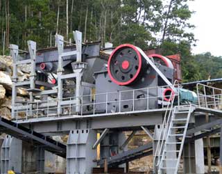
[image: (135-6-2)] SAG Mill Circuit Example — Gold Processing SAG mill circuit example for gold processing [image: (135-6-3)] AG/SAG Mill. AG/SAG mills are normally used to grind run-off-mine ore or primary crusher product. Wet grinding in an AG/SAG mill is accomplished in a slurry of 50 to 80 percent solids.
WhatsAppGet PriceGet A Quote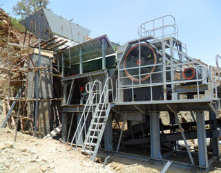
Feed 100 2.09 Concentrate 10 20.0 Tailings 90 0.1 (a) From Table 1, the Ratio of Concentration can be calculated as F/C = 100/10 = 10. If only assays are available, the ratio of concentration equals (20 – 0.1)/(2.09 – 0.1) = 10 So, for each 10 tons of feed, the plant would produce 1 ton of concentrate.
WhatsAppGet PriceGet A Quote
The process flow diagram is an essential part of chemical engineering. It conveys a process and the path of its individual components
Electronic prints fall into two basic categories, electronic schematics and block diagrams. Electronic schematics represent the most detailed category of electronic drawings. They depict every component in a circuit, the component''s technical information (such as its ratings), and how each component is wired into the circuit.
WhatsAppGet PriceGet A Quote
complete crushing plants diagram india. Crusher Flow Diagram In this crusher flow process chart the VSI Vertical Crusher ensure end item has good shape with cubic This is a Mobile Crushing Plant flow diagram and it is an integrated work team with two mobile crushers Mobile Jaw Crusher and Mobile Cone Crusher [Chat Online] Schematic Diagram Of Aggregate Crushing Plant
WhatsAppGet PriceGet A Quote
Figure 3 shows a flow sheet of the industrial aluminum production process. The processes made before the metal is sent to the cast house are called upstream processes, while the processes in the cast house to make extrusion ingots, sheet ingots, primary foundry alloys, and/or wire rods are called downstream processes.
WhatsAppGet PriceGet A Quote
The process flow diagram is an essential part of chemical engineering. It conveys a process and the path of its individual components
Fluid flow is classified into two basic fluid states at the inlet. As pressure changes occur within a throttling valve, it is possible to produce 2-phase flow at the valve’s outlet for either a liquid or gas-vapor at the inlet.
WhatsAppGet PriceGet A Quote
The Components of a Control Loop. A controller seeks to maintain the measured process variable (PV) at set point (SP) in spite of unmeasured disturbances (D). The major components of a control system include a sensor, a controller and a final control element. To design and implement a controller, we must:
WhatsAppGet PriceGet A Quote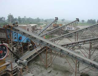
Flow sheets showing two such set-ups are shown in Figs. 3.1 and 3.2. Jaw crushers are installed underground in mines as well as on the surface. When used underground, jaw crushers are commonly used in open circuit. This is followed by further size reduction in crushers located on the surface.
WhatsAppGet PriceGet A Quote
The original operation is described briefly, much of the early EW flow sheet remains the same today. A two-stage crushing plant was operated in open-circuit. Ore was truck dumped into an Allis Chalmers 60 X 89 inch gyratory crusher and the product conveyed to a single, seven-foot standard cone crusher.
WhatsAppGet PriceGet A Quote
Impact crushers are versatile crushing machines that can be used in any stage of the crushing process. However, the features and capabilities of different impact crusher types vary considerably. Impact crushers are traditionally classified to two main types: horizontal shaft impact (HSI) crushers and vertical shaft impact (VSI) crushers.
WhatsAppGet PriceGet A Quote
Reverberatory 2 12 1500 Reverberatory 4 25-35 1300-1350 Blast 2 21-28 1150 -1300 Shaft 2 10-14 Not provided Electrothermic 1 20-24 1200-1250 Although capacity is readily available, techno/economic constraints make copper smelters unsuitable for PGM processing Source: JOM 60 smelters world wide with >100ktpa capacity
WhatsAppGet PriceGet A Quote
The crushing plant is owned and operated by NCC Roads. In its tertiary crushing stage, the plant produces high-quality aggregate products, ranging in size from 0–2 mm to 16–32 mm (see Fig. 4). The crusher is a HP4 cone crusher equipped with a medium chamber; the feed size to the tertiary crushing stage is 8–80 mm.
WhatsAppGet PriceGet A Quote
This question gives students a good opportunity to discuss the basic concept of a circuit. It is very easy to build, safe, and should be assembled by each student individually in class. Also, emphasize how simple circuits like this may be assembled at home as part of the “research” portion of the worksheet.
WhatsAppGet PriceGet A Quote
other words, crushing plants, from primary to quaternary circuits, are here to stay. There are three main steps in designing a good crushing plant: process design, equipment selection, and layout. The first two are dictated by production requirements and design parameters,
WhatsAppGet PriceGet A Quote
Processing will include 2-stage crushing (jaw crusher and cone crusher) and 2-stage grinding (semi-autogenous-grinding mill and ball mill), resin-in-leach (“RIL”), elution and electrowinning. The nominal throughput rate is projected to be 7,400 tonnes per day (“t/d”), plus 1.5 additional years at a lower rate from residual stockpile feed, for a total 9.5-year mine life.
WhatsAppGet PriceGet A Quote
ISO 9001:2000 Level II Flow Charts Printed 11/17/04 9:10 PM Page 4 2002 Cayman Business Systems Rev: Release Print: Wednesday, November 17, 2004 Elsmar.com Example Flow Charts Slide 4 Required Level II Flow Charts (Procedures) ° 4.2.3 Control of Documents ° 4.2.4 Control of Quality Records ° 8.2.2 Internal Audit ° 8.3 Control of Nonconformity
WhatsAppGet PriceGet A Quote
2. Give students a standard photocopy of a floor plan (see the end of this Activity Plan) that includes a kitchen and have them draw one or two 12-device circuits using electrical symbols and paths for circuits as shown in the floor plan drawing (Figure 5). Note: Page 59 in the Electrical Code Simplified Book will help students to understand how
WhatsAppGet PriceGet A Quote
Chemical Engineering Design Principles Practice and Economics of-Plant and Process Design
WhatsAppGet PriceGet A Quote
other words, crushing plants, from primary to quaternary circuits, are here to stay. There are three main steps in designing a good crushing plant: process design, equipment selection, and layout. The first two are dictated by production requirements and design parameters,
WhatsAppGet PriceGet A Quote
10.2.2. Installations and facilities in the design stage In new installations, quantification of the noise problem at the design stage may range from simple to difficult but never impossible. At the design stage the problems are the same as for existing installations; they are identification of the source or sources, determination of the
WhatsAppGet PriceGet A Quote
Fig. 7: A gas-turbine engine with two-stage compression with intercooling, two-stage expansion with reheating, and regeneration. When intercooling and reheating are used, regeneration becomes more attractive since a greater potential for regeneration exists. The back work ratio of a gas-turbine improves as a result of intercooling and reheating.
WhatsAppGet PriceGet A Quote
The flow sheet of a thermal power plant consists of the following four main circuits: (a) Feed water and steam flow circuit. (b) Coal and ash circuit. (c) Air and gas circuit. (d) Cooling water circuit. A steam power plant using steam as working substance works basically on Rankine cycle.
WhatsAppGet PriceGet A Quote
short circuit currents are expressed in MVA or kVA) Above 2500kVA with 400MVA available at medium voltage primary. SSCA = 3,011/((2500/400,000) +(5.75 X 0.925/100)
WhatsAppGet PriceGet A Quote
HYDRAULIC CIRCUIT DESIGN AND ANALYSIS A Hydraulic circuit is a group of components such as pumps, actuators, and control valves so arranged that they will perform a useful task. When analyzing or designing a hydraulic circuit, the following three important considerations must be taken into account: 1. Safety of operation 2.
WhatsAppGet PriceGet A Quote
 WhatsAPP 24h online service


 24h Online Chat


